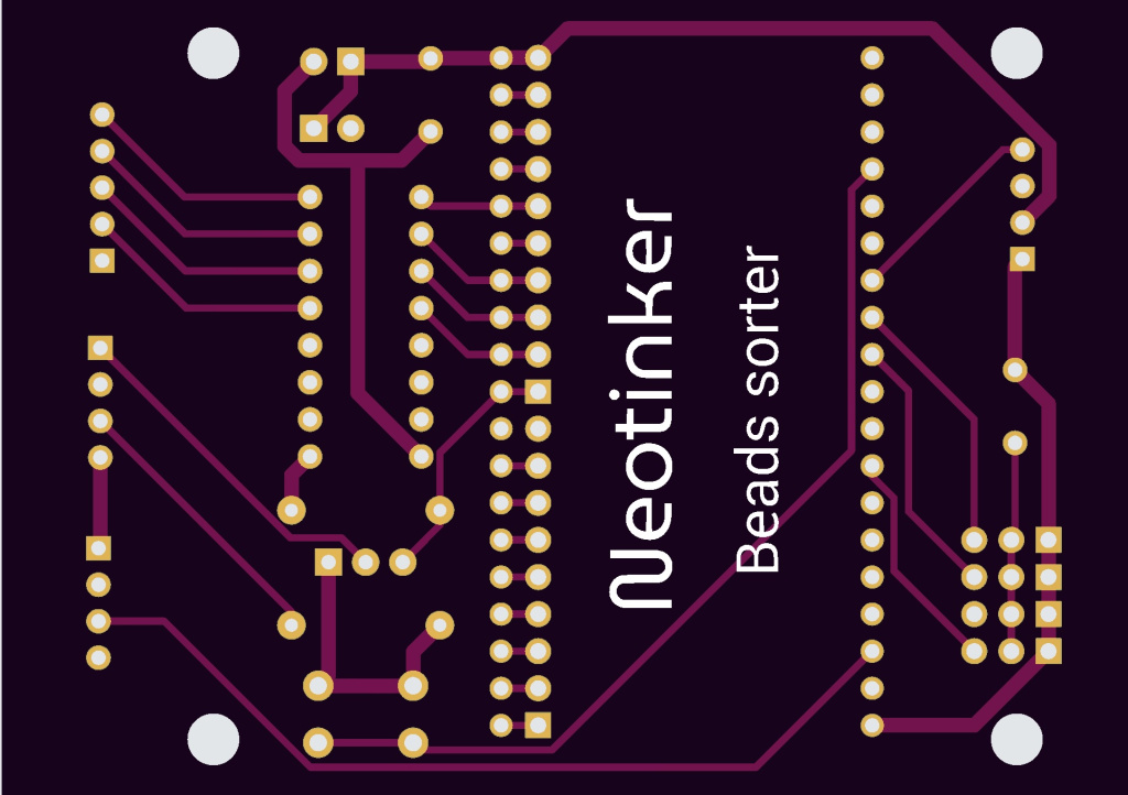
Beads sorter electronics
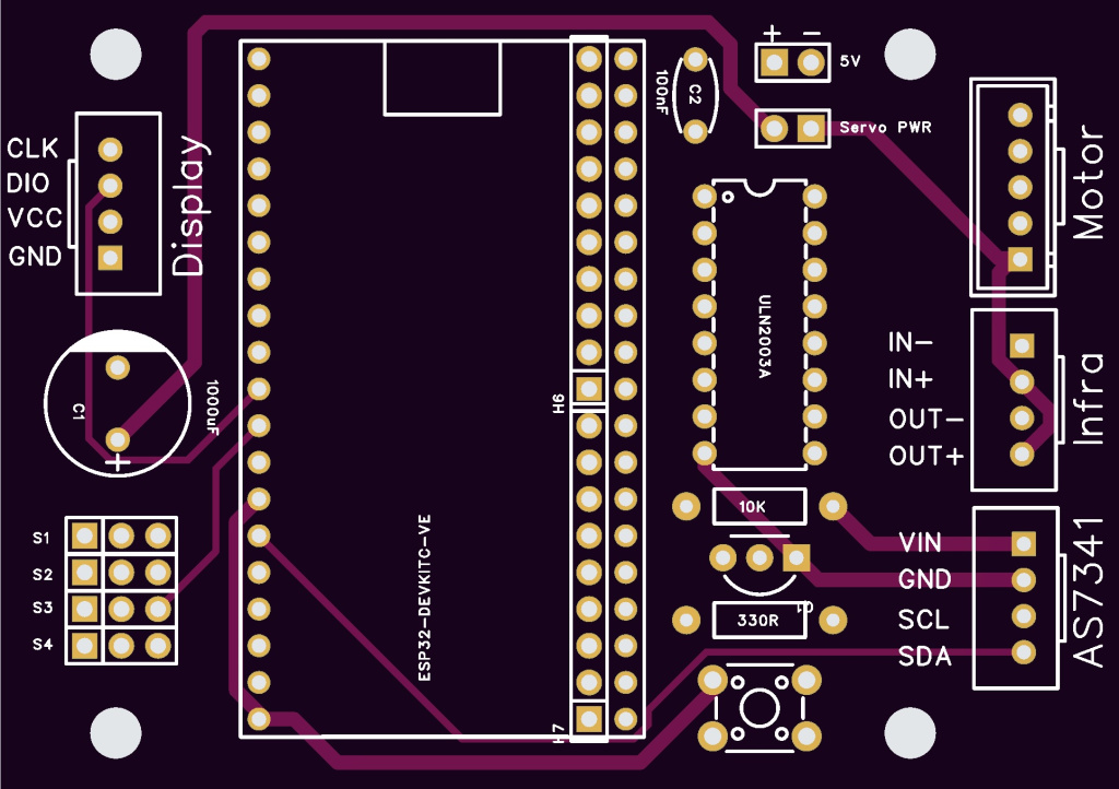
Beads sorter electronics
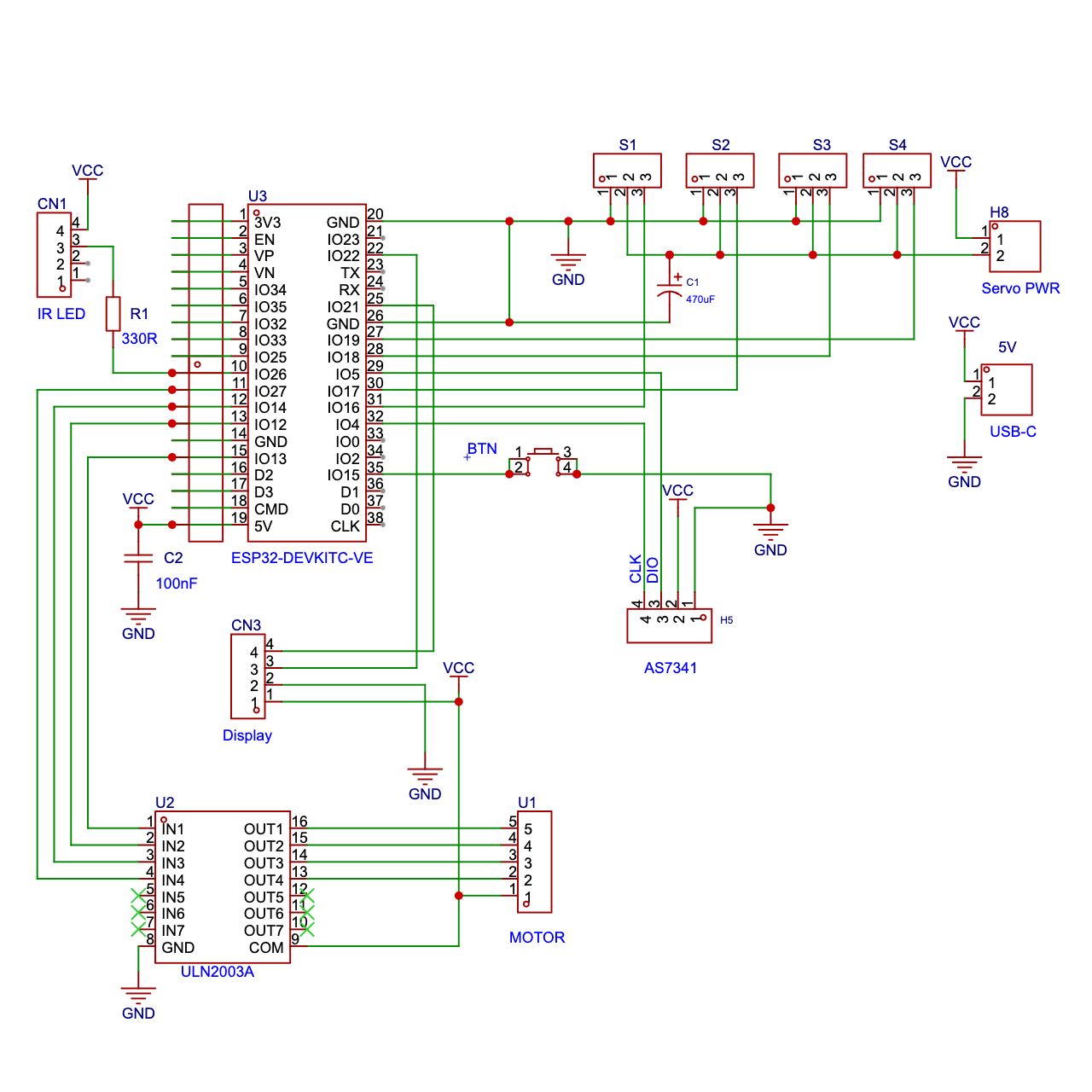
The core of electronics is ESP32 developmnet board 38pins.
It is powered through an external power source via USB-C connector. Servos may be disconnected from power by a jumper switch. It is useful for debugging and software upload. Normally these two pins must be connected, you can even solder a wire instead of jumper.
There are two capacitors on the power circuit. Electrolytic 470-1000µF to cover servos peaks and a small ceramic 100F to filter power to ESP32. Actually there are some capacitors on module too so this one is not necessary.
The stepper motor is powered through ULN2003A. It is connected to ESP32 on GPIO pins 27,14,12,13.
4digit 7segment display with TM1637 I2C driver is connected on GPIO 4 (CLK) and 5 (DIO).
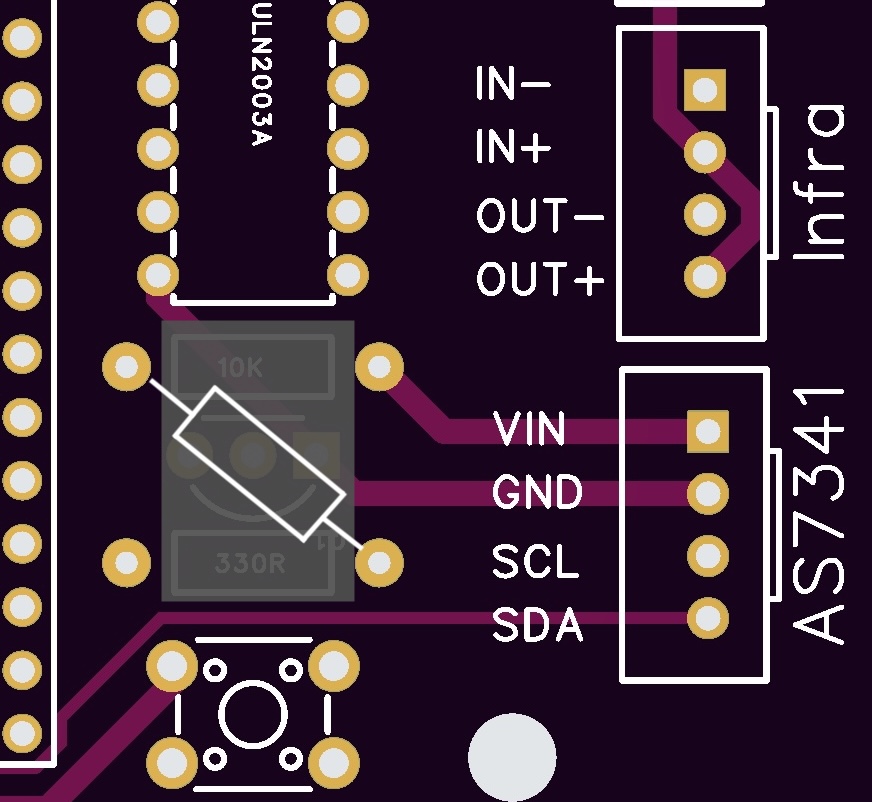
The circuit of the IR gate was changed from the first design and PCB does not reflect the change yet. Now there is no IR receiver, the functionality is on AS7341. So there is no transistor, no 10k resistor. Resistor 300R is connected from connector IR connector to GPIO 26. See the image with PCB detail. Also the cable needs only two wires.
Control button may be soldered directly on PCB, actual 3D design uses external push button with two wires and faston connectors.
Servos are connected to connectors S1-S4. Minus pole wire, usually the darkest one (black or brown) goes to the left - marked pin. S1 is the least significant bit - bottom servo. S4 is a top servo. In fact if won't follow this order, it will work anyway.
When you solder the XH connectors, keep the right orientation. There is a mark on the PCB for the side cutout. If fact you still have a second chance to solder wires correctly on the other side. See the image for details.